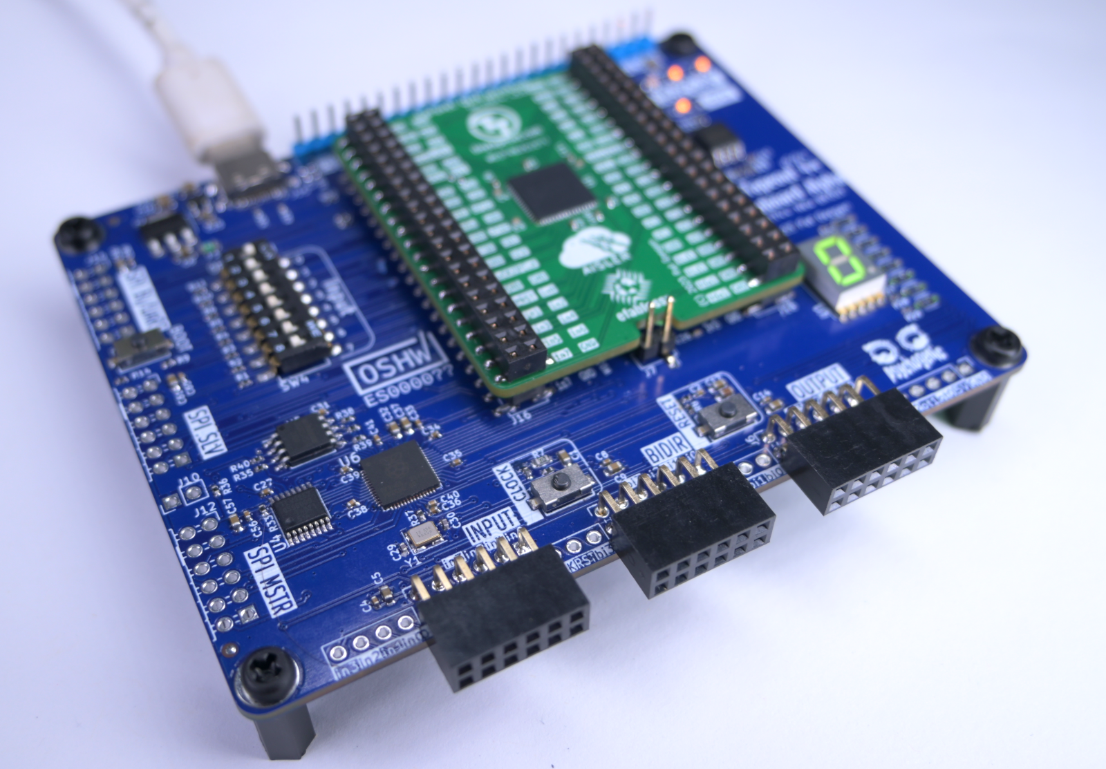
Demo board for TinyTapeout 4 and beyond.
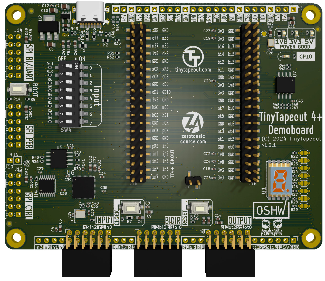
This demonstration PCB allows you to interact with TinyTapeout projects in 3 ways:
- directly, using the input DIP switches and 7-segment display;
- via breadboard or extension boards through PMODs; or
- by interacting through the on-board RP2040
Beta prototypes have been assembled and are in testing--looking pretty good! Feedback and discussion are welcome on the Discord #pcb channel, specific issues should be posted here on github.
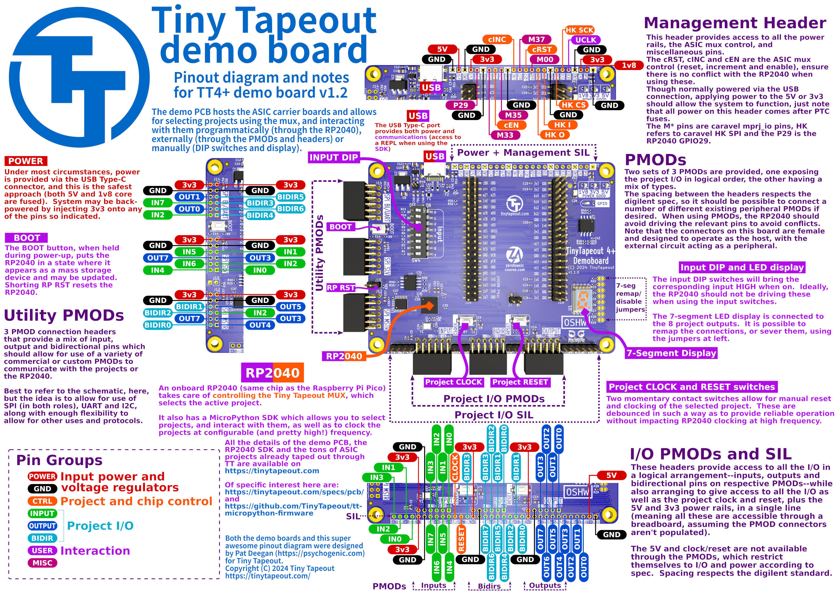
The full schematic is available as a PDF but the gist of it is:
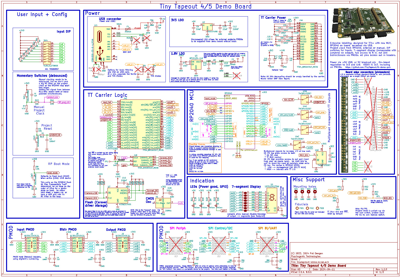
The RP2040 is responsible for selecting projects, using the multiplexer and under most circumstances providing the clock for the projects. It may, thereafter, interact with the design via it's connections to the input, output and bidirectional pins.
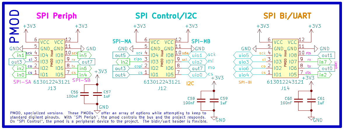
Another option is to use the various PMOD and pin headers to tie external circuitry to the design. PMODs are provided in two varieties: straightforward I/O (where one PMOD is dedicated to each of in/out/bidir pins) and "standard" PMODs, that are mapped (mostly) according to specs to allow for SPI, I2C and UART extension boards to be plugged in (this assumes the project has been designed with this in mind, with I/O tasked accordingly).
In addition with interfacing directly with projects via the RP2040, extensions and interaction with the ASIC is possible through two sets of PMODs on the demo boards.
The three on the bottom provide access to all the project I/O in a logical fashion, with inputs, bidirectional pins and outputs available on their own distinct headers.
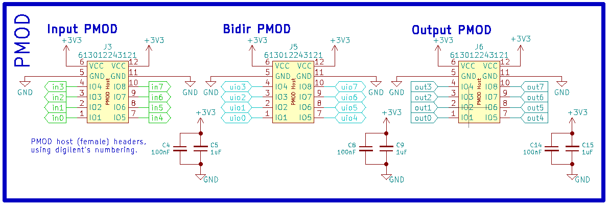
This is nice and orderly and gives you access to all the pins, but extension boards will often need to span at least two, and sometimes three, distinct headers.
In the hope of providing simpler support for interfacing peripheral modules, an additional set of PMODs pinouts were added on the left side of the PCB. These provide various mixes of in, out and bidirectional pins that should allow a variety of uses
It is likely that not all the headers will actually be populated on delivered PCBs, but these are throughole components which makes stuffing them in after the fact relatively easy.
Both sets of PMODs respect the digilent specification in terms of spacing, and are host side pinouts: modules connecting to these must be wired as PMOD peripherals, and can be powered via the supplied 3v3 rails.
| TT Pin | RP2040 Pin | I2C | SPI | UART |
|---|---|---|---|---|
| ui_in[0] | GPIO9 | SPI1.cs | ||
| ui_in[1] | GPIO10 | SPI1.sck | ||
| ui_in[2] | GPIO11 | SPI1.tx | UART1.rts | |
| ui_in[3] | GPIO12 | UART0.tx | ||
| ui_in[4] | GPIO17 | SPI0.cs | ||
| ui_in[5] | GPIO18 | SPI0.sck | ||
| ui_in[6] | GPIO19 | SPI0.tx | UART0.rts | |
| ui_in[7] | GPIO20 | UART1.tx | ||
| uo_out[0] | GPIO5 | UART1.rx | ||
| uo_out[1] | GPIO6 * | UART1.cts | ||
| uo_out[2] | GPIO7 * | |||
| uo_out[3] | GPIO8 * | SPI1.rx | ||
| uo_out[4] | GPIO13 | UART0.rx | ||
| uo_out[5] | GPIO14 | UART0.cts | ||
| uo_out[6] | GPIO15 | |||
| uo_out[7] | GPIO16 | SPI0.rx | ||
| uio[0] | GPIO21 | SPI0.cs | UART1.rx | |
| uio[1] | GPIO22 | I2C1.sda | SPI0.sck | UART1.cts |
| uio[2] | GPIO23 | I2C1.scl | SPI0.tx | UART1.rts |
| uio[3] | GPIO24 | I2C0.sda | SPI1.rx | UART1.tx |
| uio[4] | GPIO25 | I2C0.scl | SPI1.cs | UART1.rx |
| uio[5] | GPIO26 | I2C1.sda | SPI1.sck | UART1.cts |
| uio[6] | GPIO27 | I2C1.scl | SPI1.tx | UART1.rts |
| uio[7] | GPIO28 |
* These pins are multiplexed. They are connected to the RP2040 when GPIO1 is high.
- The PCB is licensed under the Apache2 License
- The documentation is licensed under the CC0
- OSHWA registration CA000047