I am considering selling assembled adapters. I want them to be affordable, accessable, and quality. If you're interested in purchasing one, you should contact me on discord; Angst#4857, or email me at angst4857@gmail.com
This adapter modifies analog stick input values. For use with Legend of Zelda: Ocarina of Time.
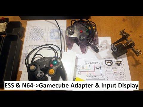
This version supports both N64 and Gamecube controllers. Selection is automatic. Just plug in a controller.
This version has an input display and works with the newest version of nintendospy (not the 2014 release).
This adapter also functions as a generic n64 to gamecube controller adapter, although I cannot guarantee that the button mapping will work for all games.
Ocarina of Time (OOT) on Gamecube (GC) and Wii run on Nintendo’s emulator called Virtual Console (VC). VC maps the GC controller values to certain in-game values. The algorithm poorly recreates the feel of the N64 version of OOT. This ESS-Adapter interprets controller input and scales/maps it to compensate for the VC map. Applying the inverse of the function means that we cancel out the bad VC map and get a result as close as possible to the original N64 analog stick range.
By taking the typical Gamecube analog stick values (top left) and applying the inverse of the VC map function (top right), they effectively cancel each other out. We can then do our own scaling and are left with an analog stick map (bottom left) That closely resembles an original n64 controller (bottom right).

Because of the nature of the VC map function, some in-game analog stick values are not possible, Hence the slightly jagged appearance of the bottom right graph. We pick the closest value.
Unreachable VC analog values:
8,13,17,22,25,28,31,34,37,39,42,45,46,49,51,53,55,57,59,61,62,64,66,68,69,71,73,74,76,78,79,80
Currently this code only works with 16MHz Atmel AVR boards due to some of the supporting libraries having AVR specific assembly code.
Support for this adapter, and adapters using Nicohood's Nintendo Controller Library has been added to the newest verions of Nintendospy, and Retrospy but must be downloaded and compiled.
I have compiled my fork of retrospy so you don't have to:
https://github.com/Skuzee/RetroSpy/releases
You may need to check Options-> Don't Filter COM Ports. To see the arduino.

Youtube Video Click Below
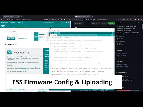
Download Arduino IDE
https://www.arduino.cc/en/software
Download and unzip the github files.
https://github.com/Skuzee/ESS-Adapter/archive/refs/heads/master.zip
Open the ESS-Adapter.ino file with Arduino IDE
Tools->Board->Board Manager
Search "Sparkfun"
Install "SparkFun AVR Boards"
Close board manager.
Plug ESS adapter into PC via a good USB cable.
Select Tools->Boards->SparkFun AVR Boards->SparkFun Pro Micro
Select Tools->Processor->ATmega32U4 (5V 16MHz)
Select Tools->Port->COM_X (Usually the highest number, not usually 1 or 2)
Click the UPLOAD button. ctrl+U
If this process does not work, try a different cable, different port, or restart your PC. COM ports can be finicky.
You can use the arduino IDE Serial Monitor ctrl+shft+M to view the settings menu as text and adjust settings easily.

Connecting the adapter to a computer via usb and opening a serial monitor (like the one in the Arduino IDE) will allow you to view the current settings. BAUD 115200
Settings are saved in EEPROM and persist through power cycles.
Currently when OOT or Yoshi Story is selected as the active button map, the ESS defaults back to ON. Generic Map does not have ESS functionality and defaults to OFF.
The 'factory default' settings are: Game: OOT, ESS: ON, Input Display: ON, Trigger Fix: OFF, Trigger Threshold: 100.
Gamecube Controller:
Press and Hold L and R triggers all the way in.
Press X Y and Start for ~3 seconds to reset the controller.
Keep L and R held while changing settings.
- D-pad Left/Right will change between Games. Currently There is OOT, Yoshi Story, and a Generic Map. *Affects which N64 button map is used, and what ESS map is used. (Currently only OOT ESS Map Exists)
- D-pad Up Enables ESS. *ESS defaults to ON when game is changed to OOT.
- D-pad Down Disables ESS. *ESS defaults to OFF when game is changed to generic.
- A toggles Input Display
- B Toggles L/R Trigger Fix (partial trigger press activates L and R buttons)
- Y Increase Trigger Threshold (Max of 250) *Lower is more sensitive. Typical Controller has a physical range of ~30 to 230.
- X Decrease Trigger Threshold (Min of 10)
- Z Reset Settings to Default. *Pressing Z, and then exiting the settings menu will reset the settings to "factory default". Press Z again to cancel.
N64 Controller:
Press and Hold L and R buttons.
Mash Press all 4 c buttons at once momentarily.
Keep L and R held.
- D-pad Left/Right will change between N64 button mappings. Currently There is OOT, Yoshi Story, and a Generic Map.
- D-pad Up Enables ESS. *ESS defaults to ON when game is changed to OOT.
- D-pad Down Disables ESS. *ESS defaults to OFF when game is changed to generic.
- A toggles Input Display
- Z Reset Settings to Default. *Pressing Z, and then exiting the settings menu will reset the settings to "factory default". Press Z again to cancel.

The n64 generic button map might not be very useful unless maybe you're tying to play a Gamecube game with an N64 controller? (That doesn't need X and Y).
Any digital input pins will work. Make sure you have them set correctly at the top of the .ino file. Depending on the board and layout sometimes I use different pins, so double check. Pins 10,14,15,16,18,19 are used for optional RGB indicator lights.
Pin 2 is the default data pin for the Wii.
Pin 4 is the default data pin for both controller types.
You CANNOT plug two controllers into the same pin at the same time without error.
If you want two plugs on the same adapter use one pin per controller type.
(i.e. PIN 4 for GC controller, PIN 3 for N64) Each with their own pull-up resistor.
Both Common Cathode and Common Anode LEDs work and setting can be set in extras.hpp
LED 1: Red pin 10, Green pin 16, Blue pin 14
LED 2: Red pin 15, Green pin 18(A0), Blue pin 19(A1)
There are too many variations for me to correctly suggest how to hook power to the arduino directly from the Wii.Each Arduino has different mosfets/diodes/regulators/wiring. The absolute SAFEST way to power your arduino is from USB only! That means using a short usb cord to one of the wii usb ports, or to your PC (for use with the input display function.)
If you don't intend to use the input display, or you want it to work without the usb cable, it's possible to connect the 5v wire from the controller cable to the arduino directly. As stated above, every arduino is different and I highly suggest you use a diode and know what you are doing.
- Arduino UNO: The safest way to power would be either from a USB cable only (connected to the Wii or computer). It's possible to power it from the Wii 5v controller wire using a step-up DC-DC boost converter (~7v-9v) to the barrel jack.
- Arduino Nano: Power the board from the Wii 5v wire through a Schottky diode to the 5v pin (not the VIN pin)
- Sparkfun Pro Micro 5v: Power from the Wii 5v wire through a Schottky diode to the VCC pin (not the RAW pin). Make sure PCB jumper J1 is not soldered closed.


The following wiring information will reference Nintendo's Gamecube coloring scheme!
Be warned, most gamecube extension cables are different.
| Nintendo Color | Use | Notes |
|---|---|---|
| Yellow | 5v Supply | |
| Red | Data 3.3v | |
| Green | Ground | |
| White | Ground | (Shown as Grey in schematic) |
| Black | Shielding | (May not be present on some cables) |
| Blue | 3.3v Supply |
At a minimum you'll need:
- A 16MHz Atmel AVR Arduino/Clone.
- One or Two 750 ohm Resistor (500ohm-1000ohm would work in a pinch.)
- A soldering iron.
- Tools to cut and strip wire.
Depending on what components you use, you may want:
- Heat shrink tubing
- A project enclosure
- Small cable ties for strain relief.
- Prototype PCB/Perf board.
- Straight and Right Angle pin headers.
- Dupont female plug crimp terminals & crimping tool.
- Assorted lengths of jumper wire.
- Kapton tape.
Join our Ocarina of Time Speedrunning Discord to chat and ask any questions: Contact Angst#4857 in the #adapters-and-inputdisplays channel.