When working on a dynamic system, either to control it or to study its stability or what ever, we find ourselves stuck not knowing its parameters.
Scrolling down datasheets and finding out each parameter of each component of the system is a way of doing, but is it the most efficient way?
To answer the efficency question, let's look at a brief exemple.
Let's imagine a plane flying and all of a suddent one of its wings broke up or got stuck in an unexpected 70-80 Km/h wind or finds itself overloded. You got the idea !
These unexpected changes impact jurasticly the dynamics of the system and in consequence the system's parameters change.
These changes are called uncertainties and in a dynamical system uncertainties happen frequently. And they always exist due to modeling errors, measurement inaccuracy, mutations in the evolutionary processes, environnment variations and so on.
In order to work with a system with structured and unstructured uncertainties we have to modelise it in a recursive way so it changes and adapts to dynamics changes.
A way to do so is the Recursive Least Square algorithm (RLS) for system's parameter identification. This estimation theory refers to calculating the coefficients of a model from a set of inputs and outputs.
The goal of this algorithm is to estimate the coefficients of the transfer function of the system given the inputs and output as shown in the block diagram down below :
                                                  _ _ _ _ _ _ _ _ _ _ _ _
                              Model input U(k)   |                       |   Model Output Y(k)
                              ------------------>| Model to be estimated |------------------------->
                                |                |_ _ _ _ _ _ _ _ _ _ _ _|         |
                                |        _ _ _ _ _ _ _ _ _ _ _ _ _ _ _ _ _ _ _ _ _ |
                                |       |        _ _ _ _ _ _ _ _ _ _ _ _ _
                                |        ------>|                         |  Estimated output Y'(k)
                                 -------------->|         Estimator       |------------------------->
                                                |_ _ _ _ _ _ _ _ _ _ _ _ _|
RLS method for system identification is a least square method so its main idea consists of minimizing the cost function J as the sum of squares of the error terms.
N : The number of samples
We define the estimated transfer function Y'(k) as follows :
We can then write
with
with:
- n: The system Order
- N:The number of samples at t=N.Ts (Ts = 1/fs sample time)
With these definitions and after mathematical developpement we define a recursive algorithm that gets updated each sample time with a set of inputs and outputs and generates an adaptive transfer function at each Ts. We define a correlation matrix related to the covariance of Theta
A varying gain K:
thus we define the updated transfer function coefficients:
With the recursive equations in place, I will give a brieve description of the implementation of RLS algorithm on a NUCLEO-STM32H723ZG board.
And testing it's performance on a DC Motor.
I will present in this section the steps I have done to validate and implement RLS Algorithm.
I first started by validating the model on Matlab because it was more practical in the implementation and the fastest way to test the efficency of my RLS algotithm.
So I collected Input (Voltage) and Output (Speed) data from the Microcontroller using semi-hosting feature.
The input signal:
- t = N/Fs.
- N:Number of samples at t and Fs:Sampling Frequency.
I aimed to choose the input signal as a combination of sinusoids in order to have a diverse set of data for testing.
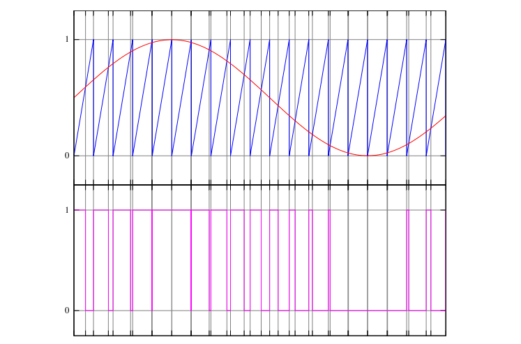
Since I am testing the model on a DC-MOTOR with NUCLEO-STM32H723ZG board, I will be using the PWM Timer's feature to generate this Input signal with varying the Duty Cycle as shown below :
The DC-MOTOR is equiped with an encoder so we can either measure the motor speed using the Timer's Input Capture feature or its position using Timer's encoder Mode feature. In our case we will be modelling The transfer function H(z) of the DC-MOTOR with the voltage delivered to the motor as an input and the speed (Measured) as an output.
Here I present an exemple of the algorithm's response with 1000 samples and Fs = 100 Hz on the DC-MOTOR:
The plotted image down bellow represents the measured output response compared to the simulated output response (Simulated by the estimation algorithm).

- RLS_Data_Acqu folder contains the algorithm of input and output data acquisition using semi-hosting feature.
- The RLS_DC folder contains the implementation of the algorithm on the NUCLEO-STM32H723ZG board.
- Matlab_RLS folder contains data files and the implementation of the algorithm on Matlab.